Translate

Showing posts with label distribox. Show all posts

March 11, 2013

#Electronic #Box for lighting information

electronic enclosure
This modular box can contain easily electronic components and lighting signals.

Distribox is a distribution box which can be also used to contain #lighting arrows or coloured #signals.
Distribox series is modular and dimensions can be according to customer’s project.
Advantages:
  • Small dimensions
  • Weightless
  • Good water proof
  • High efficiency
  • Low consumption
  • Design upon request as well

March 04, 2013

Electronic Box with power #LED #lamps

High efficiency lamps
Shield box with LED lamps. Box dimensions 31 mm x 93 mm. Smaller and bigger dimensions are available.


Distribox is a distribution box which can be also used to contain LED #lights and illuminate dark angles of the #machine.
Distribox series is modular and dimensions can be according to customer’s project. 

Advantages:
  • Small dimensions
  • Weightless
  • Good water proof
  • High efficiency
  • Low consumption
  • Design upon request as well

January 18, 2013

Cover for an #electronic #box

A Distribox with rear #connection can also become the #cover of a box for electronic circuits.
The number and the type of connectors can be changed according to the project needs.
In this way the customer can put inside his own circuit, even of big dimensions.
Here below the most common sizes are listed
(L x W x H mm):
120 x 80 x 55
120 x 80 x 85
160 x 80 x 55
160 x 80 x 85

Distribution box with M12 or M8 connectors
Shield's cover with plug or socket connectors for electronic box.


December 12, 2011

Triple #Distribox

Star shape Distribox,
triple line M12 female sockets,
from 3 to 15 sockets,
for #sensors #electrovalves, etc.


for sensors and electrovalves
Star shape Distribution Box with M12 angled connectors

June 17, 2011

Triple line Distribox

Space saving
top mounting #distribution #box,
triple line #M8 sockets,
from 6 to 15 sockets,
for sensors or small signals connection, etc.

Connection of sensors or small signals
Triple Line Distribox

June 10, 2011

SK23 series Distribox + SF23 series Distribox

Distributor for connection of sensors
Distribution box with M8 female socket connectors


#Distribution #boxes,
top mounting #M8 sockets,
from 4 to 10 sockets,
with or without signalling Led,
for connection of sensors, etc.;
special circuits on request.


Distributor for connection of sensors
Distribution box with narrow spacing and M8 socket connectors

Distribution boxes, narrow pitch,
top mounting M8 sockets,
from 4 to 10 sockets,
with or without signalling Led,
for connection of sensors, etc.;
special circuits on request.


February 17, 2011

SD20 series Distribox + SK20 series Distribox

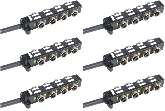
distributor M12 with small profile
Distribution box M12 socket with flat profile for application with small space.

#Distribution #box,
side mounting #M12 sockets,
with small space profile,
from 2 to 10 sockets, 1 or 2 signals each socket,
with or without signalling Led,
for connection of sensors, actuators, etc.;
special circuits on request.


distributor with M12 connectors
Distribution box with M12 socket and top mounting.

Distribution box,
top mounting M12 sockets,
from 4 to 10 sockets,
1 or 2 signals each socket,
with or without signalling Led,
for connection of sensors, actuators, etc.;
special circuits on request.


June 25, 2010

#Current-carrying #Capacity. Ambient Air and Cable Temperature

How to choose the #cable #section.
The current flow in a connector and in its cable generates heat, thus a temperature rise. Any connector or cable insulating material has a maximum safety temperature that should never be exceeded to ensure the stability of their mechanical properties.
After verifying the insulating material quality and the working ambient air temperature, the maximum current-carrying capacity permitted in the connector can be calculated in function of the terminals size and the conductors section.
Current Carrying CapacityTable 2 on page http://www.shield.net/files/catalogue/support/2.2.pdf shows the maximum current values for a pvc cable (quality 70°C) with 2 or 3 wires without metal sheath, with copper conductors, employed for normal use and inserted into cable tray. For open air applications a current about 10% higher is admitted.
The ambient air temperature is measured around the cable, for example inside the cabinet or close to the machine interspaces. The right ambient air temperature is found after the normal functioning of the machine, under full load for a sufficient period of time, without taking into account the variations of the temperature due to heating of the cable. If the use does not require a higher temperature project, the conventional value of 40°C (IEC 60204-1) must be considered.
The table takes into account that in most of the machines not all cables are used simultaneously for long periods. In special cases (many wires used at the same time or high ambient air temperatures), a reduction factor of between 0,3 and 0,9 must be used to reflect the overheating of cables in the same group, otherwise verify that the temperature remains within the limits allowed. Particular attention must also be paid to vertical and limited ventilation routes.
Values and comments refer to IEC 60204-1 (Machinery Safety, edition October 2005) and IEC 60364-5-52 (Wiring Systems Security).

#Current-carrying #Capacity. Cable Voltage Drop

Cable choice.
An important element of assessment is the length of the cable. Each meter of the cable causes a voltage drop proportional to the value of the current that runs through it, if cosf = 1 we have: V = IxR.
Max Cable CurrentV = voltage drop, I = current, R = resistance of the cable. In the case of inductive loads (solenoid valves, motors, etc.) or with variable currents, the higher current peak must be considered to avoid even temporary loss of power, which could hinder the proper functioning of the equipment. The longer is the cable, the greater the #voltage #drop, the IEC allows maximum values drop from 3% to 5% of rated voltage. Greater values are admitted only for the current peaks (e.g.: engines starting), if they do not create functioning problems. To minimize the voltage drop the cable section should be increased. Here are some tables that can help to easily calculate the minimum theoretical cable section. See tables 3 and 4 on the page http://www.shield.net/files/catalogue/support/2.2.pdf.
For example, an average continuous current 1 A with section 0,34 mm2 and cable length 10 m generates a voltage drop of 1,3 V, which is approximately 5% of 24 V.

June 04, 2010

#Spider #Box

The Spider Box is a modular solution: simple connections or complex bonded junctions according to client's design can be wired and over-moulded with an efficient cost/quality rate. Assembling with shielded or unshielded cables. Up to 25 #cables #connections with multiple wires can be linked together. Electronics: standard circuit or built-in custom electronic circuits design are available. Hybrid versions with M8 and M12 connectors + direct cable junctions are also available. It's the solution to reduce the design and cables assembling time in your project.
Some of the main advantages:
- Even a not skilled worker can assemble the machinery electrical parts.
- Easy maintenance for the machinery electrical parts.
- It reduces the stock part numbers.
- Possibility to built-in sophisticated electronic components as well.


Shield mixed spider with industrial cable connectors. 3 modules spider splitter with electrovalve, M12 and Phoenix type female connectors.SD3A5N7 Shield hybrid wiring: direct cables + M8 / M12 top mounting sockets. Modular spider splitter. The picture shows a distribution box with 5 blocks. Shield spider splitter for hydraulic application. 3 modules spider with 6 electrovalve connectors. Very useful to reduce the wires quantity directed to the central board. Spider splitter